

Stratification in commercial thermal stores and buffer vessels
Diffusers, sparge pipes and baffle plates: what each one does, why a stratified store matters to every heat pump and most of all to a CO₂ heat pump, and what the heat network code of practice asks for. We build commercial and industrial vessels to order with all three.
What stratification is
Hot water above cold, with a sharp line between
Hot water is lighter than cold: about 983 kg/m³ at 60 °C against about 1,000 kg/m³ at 10 °C.9 Left undisturbed, it floats. A stratified vessel uses that: hot water sits in a layer at the top, cold water in a layer at the bottom, and between them is a narrow transition band, the thermocline.
The density difference is under 2%, so it doesn’t take much to undo it. A fast jet from a connection, or a current set up by water entering at the wrong temperature for its level, stirs the layers together. The thermocline spreads into a thick, lukewarm middle and the vessel behaves like one mixed tank.
Good stratification is a design choice: a tall vessel, connections at the right heights, low entry velocities, and internals that stop incoming water from mixing. That last part is what this page is about.
Stratified
Narrow thermocline
Mixed
Lukewarm throughout
Why it matters
A mixed vessel wastes capacity and warms the return
Usable volume
Only water at the temperature you need is useful. A mixed, lukewarm middle is paid for and heated, but it can’t serve the load and it’s too warm to return.3,1
Return temperature
The heat source’s return is drawn from the cold connection at the bottom of the store. Keep that water cold and the heat source sees a genuinely cold return; mix it and the return rises.1
Plant efficiency
Lower operating temperatures give heat pumps higher efficiencies, and CO₂ heat pumps lose efficiency sharply when the water coming back to them is warm. Stratification protects what the heat source was selected to do.3,7
Stored heat depends on the temperature difference. A store holds heat in proportion to its volume and the difference between its hot and cold temperatures. For example, 5,000 litres charged to 70 °C over a 40 °C return holds about 174 kWh. If a fifth of the height is a mixed band, too cool to serve the load and too warm to return, the usable figure drops to about 139 kWh: you’ve paid for a 5,000 litre vessel and got a 4,000 litre one. The 2015 consultation draft of CP1 asked designers to allow for this mixing zone when sizing a store, and the draft TS1 proposes tall stores to keep it small.3,1
The return temperature governs the system. For a given flow temperature, a low return temperature cuts the flow rates a heat network needs, and if design return temperatures aren’t maintained in operation, the network’s capacity falls; lower operating temperatures also give higher efficiencies with heat sources such as heat pumps.3 The water at the bottom of the store is the heat source’s return. A mixed vessel hands it back warm.
Every heat pump prefers it. A heat pump’s efficiency falls as the temperature it has to deliver rises. On the ideal (Carnot) cycle with a 0 °C source, delivering at 51 °C instead of 50 °C costs about 1.7% of the COP; real machines run below the ideal, so use the manufacturer’s data for the actual figure. If the store mixes, the water at the top is cooler than the heat pump made it, so the flow temperature has to be set higher to hold the load at its setpoint, and the heat pump pays for that in efficiency. Heat network guidance makes the same link: lower operating temperatures give higher efficiencies with heat pumps.3
CO₂ (R744) heat pumps
Why a CO₂ heat pump needs a genuinely cold return
Carbon dioxide’s critical point is about 31 °C (at about 74 bar).9 Above that temperature it can’t condense, so a CO₂ heat pump heating water runs a transcritical cycle: it gives up its heat above the critical point, in a gas cooler rather than a condenser.
In a condenser the refrigerant releases most of its heat at one temperature. In a gas cooler it cools steadily all the way through, from compressor discharge temperature down towards the temperature of the water coming in. That long temperature glide is why CO₂ is suited to heating water through a large rise in one pass: Mitsubishi Electric’s QAHV, for example, delivers water from 55 °C up to 90 °C.8 But it only works if the incoming water is cold.
The CO₂ can’t leave the gas cooler cooler than the water entering it. With a cold return, the CO₂ leaves cold and dense, and after the expansion valve more of it is liquid, ready to absorb heat in the evaporator. With a warm return, the CO₂ leaves warm; after expansion more of it has already flashed to vapour, which absorbs no more heat by evaporating. To get the best efficiency, as much heat as possible has to be taken out of the CO₂ in the gas cooler, which needs cold entering water. A 2024 feasibility study for the Bonneville Power Administration makes the same point, calls the limit on entering water temperature a disadvantage of CO₂ as a refrigerant, and describes a CO₂ unit whose efficiency drops significantly with entering water above about 32 °C (90 °F).7
Manufacturers set their limits accordingly: Mitsubishi Electric, for example, says its QAHV achieves its large temperature rise when the inlet water is below 29 °C.8 Research at Oak Ridge National Laboratory modelling a CO₂ heat pump water heater looked at water supply temperature and tank stratification among its parameters, and describes water temperature stratification in the tank as an essential requirement for higher performance from CO₂ heat pump water heaters.6 Check the limit for the unit you’re specifying.
For the specifier: with a CO₂ heat pump, the store is the return temperature control. It has to keep a deep, cold layer at the bottom while hot water is drawn off the top, through every charge and discharge. That’s a stratified vessel with low-velocity connections and the internals to protect the layers.
Inside the vessel
Diffusers, sparge pipes and baffle plates
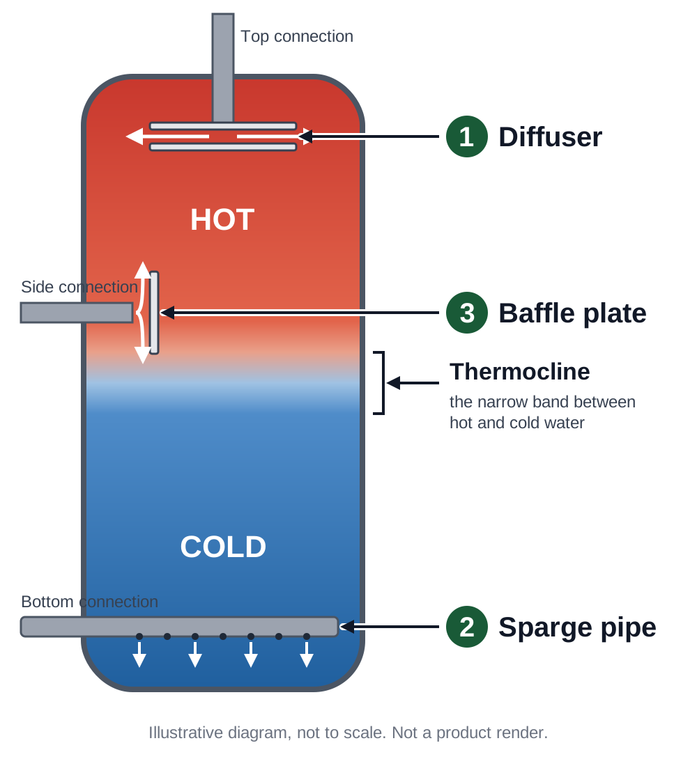
Three internal features, each for a different job. The terms aren’t used consistently across the industry, so show on the drawing exactly what you want at each connection.
- 1DiffuserSlows and spreads the flow at a connection, so it enters its own layer gently instead of jetting through.
- 2Sparge pipeDistributes the flow across the vessel through many small holes along a pipe.
- 3Baffle plateA fixed plate in the path of the incoming flow that stops it jetting through the layers.
Diffuser
Slows and spreads the flow at a connection, so it enters its own layer gently instead of jetting through.
- What it is and what it does
- A fitting inside the vessel on the end of a connection. It gives the water a much larger area to leave through than the pipe bore, so it comes out slowly and disturbs the layers less. The draft TS1’s example of good diffuser design is two horizontal circular plates at the connection, the water leaving through the gap between them.1 Because that gap faces sideways, the water spreads out along its own layer rather than driving up or down through the others.
- Where it goes
- On the connections that charge and discharge the store: the draft TS1’s example shows diffusers on the top and bottom connections.1
- When it’s used
- Wherever flow enters or leaves a stratified store. For heat network thermal stores, the draft TS1 proposes that stores be designed with internal diffusers at their entry and exit points; as a draft, that is a proposal, not yet a binding requirement.1
Sparge pipe
Distributes the flow across the vessel through many small holes along a pipe.
- What it is and what it does
- A perforated pipe running across the inside of the vessel from a connection, with holes or slots along its length. Instead of one inlet delivering all the flow at one spot, the flow is shared between many small outlets at the same level, so each carries only a fraction of it at low velocity. A CIBSE Journal design article names sparge pipes, alongside diffusers, as a way to minimise the internal mixing that ruins the thermocline.5
- Where it goes
- Neither heat network document says where a sparge pipe goes. In the diagram it runs across the base (cold) of the vessel, fed from a connection in the shell; the same arrangement can serve the top (hot). Its position is set on the drawing for each vessel.
- When it’s used
- Where you want the flow at one level spread over many outlets rather than one. The draft TS1 notes that multiple entry or exit points at the same level can reduce turbulence further than a single one.1 A sparge pipe is one way of doing that from a single shell connection. Since velocity is flow divided by area, it follows that sharing the flow between outlets matters most at high flow rates, where a single outlet would need a very large area to get the velocity down.
Baffle plate
A fixed plate in the path of the incoming flow that stops it jetting through the layers.
- What it is and what it does
- A plate fixed inside the vessel in front of a connection. The incoming jet hits it and is turned, losing its momentum, so it can’t punch across or through the vessel. The 2015 consultation draft of CP1 asked for internal baffle plates at a store’s entry and exit points, together with large connections, to minimise turbulence and promote stratification.3
- Where it goes
- Just inside a connection, at the entry and exit points.3
- When it’s used
- The 2015 consultation draft of CP1 put baffle plates at a store’s entry and exit points.3 Neither document sets out when to choose a baffle over a diffuser or sparge pipe; in the diagram a baffle sits in front of the side connection, as an illustration. Which internal suits each connection depends on its size, position and flow, and is settled on the drawing.
| Feature | Main job | How | Position |
|---|---|---|---|
| Diffuser | Slow the flow at a connection | Large outlet area; turns the flow sideways into its own layer | Top (hot) and bottom (cold) connections, as in the draft TS1’s example |
| Sparge pipe | Spread the flow across the vessel | Many small holes along a pipe; flow shared over the cross-section | Set on the drawing; across the base in the diagram, fed from a shell connection |
| Baffle plate | Stop an incoming jet | A fixed plate that turns the jet and takes out its momentum | At entry and exit points, as in the 2015 CP1 draft |
Connections and velocities
Arranging a vessel to stay stratified
- Keep entry velocities low. The draft heat network standard TS1 proposes that flow velocities through a thermal store’s diffusers be kept below 0.2 m/s.1 A CIBSE Journal design article puts the figure for water entering the tank at no more than 0.15 m/s.5
- Hot at the top, cold at the bottom. The draft TS1 proposes that the hottest water the plant can make is fed into the store’s hot inlet, and that the water at its cold inlet is no warmer than the network return.1 Water arriving warmer or cooler than the layer it enters is buoyant or heavy against it, so it rises or sinks through the layers and mixes them on the way.
- Make the vessel tall. The draft TS1 proposes a thermal store height of at least 1.5 times its diameter, and preferably 2 times, to minimise the inactive separation layer; the 2015 consultation draft of CP1 asked for at least 2, with 3 or more preferred.1,3
- Only pass the difference through the store. The 2015 consultation draft of CP1 asked for connections that carry only the difference between what the plant produces and what the load takes, not the whole demand, with the store itself acting as the common header. The draft TS1 proposes a two-pipe connection to achieve this, and proposes that a four-pipe connection not be used.3,1
- More than one store? In series. The 2015 consultation draft of CP1 asked for multiple stores to be connected in series to maximise the useful volume, and the draft TS1 proposes the same. It defines that as the top connection of one store connected to the bottom connection of the next, and proposes counting the stores’ combined height when checking the height-to-diameter ratio.3,1
- Measure it. The 2015 consultation draft of CP1 asked for at least five temperature sensors aligned vertically on each store so its operation can be monitored; the draft TS1 proposes the same, equally distributed.3,1
Worked example: what a diffuser does to velocity+
Velocity is flow divided by area. 5 litres a second through an 80 mm bore is about 1.0 m/s: five times the 0.2 m/s proposed in the draft TS1.
A radial diffuser releases the same flow through the ring between its two plates, whose area is π × plate diameter × gap. With 400 mm plates 20 mm apart that’s about 0.025 m², so the water leaves at about 0.20 m/s, and horizontally.
An illustration of the principle, not a design: the diffuser for your vessel is sized to its flows and dimensions.
Standards
What CIBSE CP1 says
CP1 Heat networks: Code of Practice for the UK is published by CIBSE and the Association for Decentralised Energy (ADE). The current edition is CP1 (2020).2 It sets minimum requirements for heat networks, from feasibility to operation; its 2015 consultation draft set these out objective by objective, including one on optimising thermal storage.3 It’s a voluntary code that has been widely adopted on heat network projects, and it applies to thermal stores on heat networks.1
The code has long linked stratification to how a store’s connections are built. Its 2015 consultation draft asked for stores to be designed to minimise turbulence and promote stratification, with large connections (so low velocities) and internal baffle plates at the entry and exit points; to allow for the mixing zone when sizing; and to be tall.3
The Heat Network Technical Standard (TS1), published in draft by the Department for Energy Security and Net Zero in November 2025, is largely based on CP1 (2020) and is intended to supersede it as the technical standard for the Heat Network Technical Assurance Scheme. It is still a draft: its provisions are proposals, and may change before the final version is issued. As drafted, it proposes that a thermal store be designed with internal diffusers at its entry and exit points, with the velocity through them below 0.2 m/s, to minimise the mixing layer and maximise the storage volume. Its example diffuser is a pair of horizontal circular plates at the top and bottom connections.1
In short: for heat network thermal stores, heat network guidance has long asked for internals at the connections to protect stratification: baffle plates in the 2015 consultation draft of CP1, and internal diffusers in the draft TS1, where they’re proposed rather than yet required. Neither document names sparge pipes; a CIBSE Journal design article lists them alongside diffusers as a way to limit mixing.5 Outside heat networks, none of this applies as a requirement, but the physics is the same for any buffer vessel or thermal store serving a heat pump.
Made to order
Built to your specification, internals included
We manufacture commercial and industrial vessels to order at Tudor House, our commercial factory in Dukinfield, to the customer’s specification, with internal diffusers, sparge pipes and baffle plates designed in.
Your size and layout
Buffer vessels and thermal stores from 10 to 10,000 litres, vented or pressurised, with the connection sizes, positions and orientation you specify.
Your internals
Diffusers, sparge pipes and baffle plates at the connections that need them, plus direct connections or single and twin coils.
Your material and standard
Mild steel, galvanised mild steel or stainless steel, built to BS 853, PD 5500 and the Pressure Equipment Directive where required.
Your drawing
A fully detailed drawing for each order, polyurethane injection insulation, and de-stratification pump sets for calorifiers that need them.
Lead times for built-to-order vessels
For buffer vessels and calorifiers, the range these vessels are built in.
Lead time
Call us for today’s lead time on 0161 343 8610.
Specifying a stratified vessel?
Send us the duty and the drawing
Volume, dimensions, pressures, connections and flow rates, the heat source and the internals you want. Our engineers will design the vessel and price it: bespoke enquiries answered within 48 hours, standard range immediately.
Common questions
Should a domestic hot water calorifier be stratified too?+
Stratification is what a heat pump wants, but stored domestic hot water also has to be controlled for Legionella. The HSE’s technical guidance, HSG274 Part 2, lists a supply temperature of at least 60 °C from the calorifier among its design principles (paragraph 2.37). In paragraph 2.25 it notes that cold water entering at the base of an indirect calorifier creates a cooler zone that may support microbial growth, says stratification in large calorifiers should be avoided, and says a timer-controlled shunt pump, circulating water from the top to the base at the time of least demand with the heat source on, should be considered so that the whole vessel reaches at least 60 °C for at least one continuous hour a day. That’s the job of a de-stratification pump set. With a heat pump heating domestic hot water, the two aims have to be designed together, and the site’s Legionella risk assessment should set the strategy; we build the vessel, the internals and the pump set to suit it. Our Legionella and safe hot water storage guide covers this in more detail.4
Is a buffer vessel the same as a thermal store?+
The names overlap. On heating and heat network circuits, both are vessels of primary water that add thermal mass and let the heat source run independently of the load. Heat network documents (CP1, TS1) say “thermal store”; buffer vessel is common in building services. What matters for stratification is the same either way: connection positions, velocities and internals.3,1
Do horizontal vessels stratify?+
They can, but for the same volume they have less height to do it in, so the transition band takes up a bigger share of the volume. That’s the reason heat network guidance gives for tall stores: the 2015 consultation draft of CP1 asked for a height of at least twice the diameter, and the draft TS1 proposes at least 1.5 times, preferably 2, while accepting a lower ratio with justification, for example where the diffuser design allows it. Where a horizontal vessel is the only option, low entry velocities and internals at every connection matter all the more.3,1
What do you need from us to quote?+
The volume and orientation, the maximum dimensions the plant room allows, the working pressure and temperature, the material, and each connection’s size, position and flow rate. Tell us the heat source (for a CO₂ heat pump, the model and its inlet water limit), which internals you want, and any sensor pockets. A schedule or drawing is ideal.
Sources
- Department for Energy Security and Net Zero, Heat Network Technical Standard (TS1), draft, November 2025 (not final: subject to change before the Heat Network Technical Assurance Scheme launches): proposed thermal storage requirements 3.8.11 to 3.8.18 (opens in a new tab)
- CIBSE and the Association for Decentralised Energy, CP1 Heat networks: Code of Practice for the UK (2020), ISBN 978-1-912034-80-2 (opens in a new tab)
- Heat Networks: Code of Practice for the UK, consultation draft (2015), published by the Greater London Authority: Objective 3.11, thermal storage (opens in a new tab)
- Health and Safety Executive, HSG274 Legionnaires’ disease: Technical guidance, Part 2: The control of legionella bacteria in hot and cold water systems (second edition 2024; Part 2 unchanged from the 2014 first edition), paragraphs 2.25, 2.26 and 2.37 (opens in a new tab)
- R. Kirkwood, “Optimising thermal store design for CHP”, CIBSE Journal, February 2020 (opens in a new tab)
- Oak Ridge National Laboratory, “Performance optimization of CO₂ heat pump water heater” (publication abstract) (opens in a new tab)
- Ecotope for the Bonneville Power Administration, “Flow Environmental Systems ANSWR CO₂ Heat Pump Feasibility Study and Applications Testing”, August 2024: section “CO₂ refrigerant and inlet water temperature” (opens in a new tab)
- Mitsubishi Electric, “High temperature CO₂ heat pump increases hot water efficiency” (QAHV), September 2020 (opens in a new tab)
- NIST Chemistry WebBook, SRD 69: thermophysical properties of fluid systems (water density; carbon dioxide critical point) (opens in a new tab)
Standards and codes are summarised, not reproduced: refer to the documents themselves for the requirements. Physical properties of water and carbon dioxide are NIST reference values, rounded; the ideal (Carnot) heat pump figure, the effect of gas cooler outlet temperature on the refrigerant after expansion, and the worked examples follow from standard thermodynamics and the formulas shown.
Help choosing and specifying
Guides and tools
- Legionella and safe hot water storageHSE L8 and HSG274 temperatures for stored hot water
- Heat pump cylinders: what to look forCoil size, storage temperature and sizing explained
- Hot water storage sizing calculatorStorage volume and reheat time, homes and commercial
- Insulation savings calculatorWhat a better insulated commercial cylinder saves a year
Need a cylinder built to your specification?
From 10 litres to 10,000 litres, our Manchester team designs, manufactures and tests every vessel in-house. We confirm and respond to every bespoke enquiry within 48 hours, and standard range enquiries immediately. If you need a price on a standard product, don’t hesitate to call and speak to one of our team on 0161 343 8610.We confirm and respond to every bespoke enquiry within 48 hours, and standard range enquiries immediately. If you need a price on a standard product, don’t hesitate to call and speak to one of our team on 0161 343 8610.We confirm and respond to every bespoke enquiry within 48 hours, and standard range enquiries immediately. If you need a price on a standard product, don’t hesitate to call and speak to one of our team on 0161 343 8610.
General technical guidance for specifiers. Worked examples are illustrations with round figures; each vessel is designed to its own duty, and the system designer remains responsible for the system.